Setting up the level

1. Set up the tripod where you have a clear
sight of the benchmark, at a similar height to but preferably higher, than the
benchmark. If possible, set up in the center of the area that you intend to
survey, or somewhere that you can see all of the site as well as the
backsight/Bench Mark, with the top plate relatively level.
Release the catches
on each leg and extend to full length, close the catches. Space the tripod legs
well apart, with the level plate about chest height of the person who will be
reading the levels. NB: the tripod needs to low enough for the smallest person
on site to use the dumpy level!
Note: Bear in mind that if at some point
you have to move the level (higher or lower, or to a new location) you will need to re-level it
and retake the backsight reading (see below).
2. Place the level head on the baseplate and attach it to the central
screw beneath the baseplate. With the telescope parallel to two of the foot
screws, level off by adjusting the two foot screws simultaneously, turning them
in opposite directions until the
level bubble is central.
Then turn 90 degrees so the telescope
points towards the third foot screw, and use the third screw to adjust the
spirit level until the bubble is central along this axis. Check again in all
directions. Now you should be perfectly level. NB: If the legs get kicked or
moved by mistake, you will have to repeat the above steps.
Taking a reading

Taking the backsight (BS)
• The first measurement that you need
to take is the backsight.
This will enable you to calculate the
height of the instrument/level (IH) from
which all other levels are calculated.
• The person with the staff should
place the bottom of the staff level on the BM or
TBM, keeping it as vertical as possible.
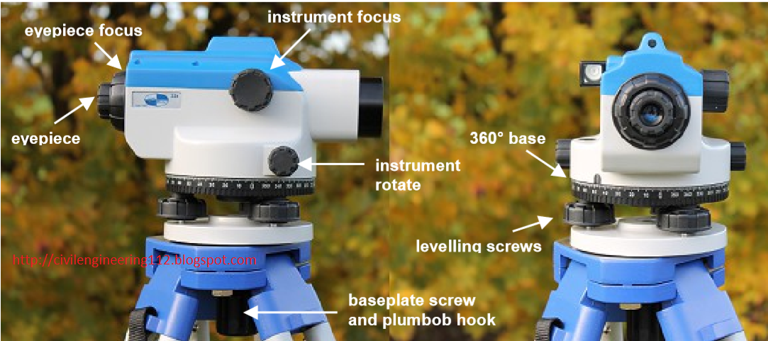
• The person at the Level rotates the
telescope until the central line/cross hairs are lined up with the staff; you
may need to focus the eyepiece first to see
the cross hairs then the telescope focus to see the numbers on the staff; use
the fine adjustment to be perfectly lined-up.
• When looking through the telescope,
you take the reading where the central or stadia
cross hairs meet, to the nearest centimeter. For example in the diagram
to the right (above) the reading would be 1.42m.

1) The leveling bubble should be central
___________________________________
Download Glober Mapper & Cracks : Click here
Download free mobile data recovery software full registered
Drfone-for-android Click here
install Android 7.1.1 in laptop or PC Click here
Or
Download Wondershare Filmora Video Editor 7.3.0.8 +
Download free mobile data recovery software full registered
Drfone-for-android Click here
install Android 7.1.1 in laptop or PC Click here
Or
Download Wondershare Filmora Video Editor 7.3.0.8 +
Serial Key Click here
Read how to Activate Autocad Civil 3 D 2018 and download X-force Cracks Click here
__________________________________________
2) Calculating the instrument height:

(IH) (or height of the Level) In order to calculate the height of the
instrument (IH; ie the height of the Level Head telescope) you add the value of
the reading you have just taken to the known value of the BM or TBM that you
are using.
3) Taking Foresight (FS):
Readings and calculating reduced levels Begin
taking height (level) readings of anything you want to illustrate on your site:
top of slope, bottom of slope, break of slope – to illustrate changes in height
and create profiles.
Mark the
location of your levels on the plan, starting at 1 (see example below) or the
next available number if returning to a survey, and read off each height
reading and record these in a separate notebook.
Make sure you write clearly and record the
date, where the survey is, what the BM or TBM is
and the initials of the people undertaking the survey.
Each time
you will have to rotate the telescope, sight on the staff in its new location,
focus and carefully take the reading, always check twice that you have read the
number correctly
Once you have taken all the levels you want, you
will need to calculate the actual height values,
or reduced levels (RL) by subtracting each
one from the instrument height (IH). This gives you the 'real' height of the
ground at the base of the staff.
Read example Click here
Page 2/3
_________________________________________
Read more:
Read how to Activate Autocad Civil 3 D 2018 and download X-force Cracks Click here
All about ↭ civil engineering 2018
No comments:
Post a Comment